Auto on off timer circuit diagram Hobby electronics circuits: simple delay timer circuits explained Simple delay timer circuits explained
Hobby Electronics Circuits: Simple Delay Timer Circuits Explained
Time delay relay using 555 timer, proteus simulation and pcb design
On off delay timer circuit diagram pdf
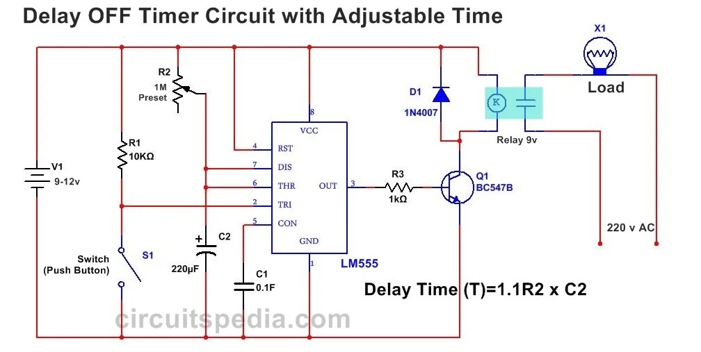
Simple delay timer circuits explained – homemade circuit projectsTimer delay relay 555 proteus pcb simulation Delay circuits timer relay explained electrical sirkuit arduino schematics sequential alarm keterlambatan transistors pressed elektronika dapatAdjustable auto on off delay timer circuit using 555 ic.
Off delay timer circuit using 555Relay timer wiring delay timing connection electricalacademia Delay relay timer off time using npn power circuit transistor diagram capacitor dc gen driveAnly delay relay buzzer contactor schematron 240v timing.

Delay timer circuits circuit simple electronic explained diagram homemade projects trigger schematics electronics seconds step two few long active has
Delay timer adjustable circuit off 555 schematic ic using auto explanation worksOff delay timer circuit diagram Time delay circuit diagramSolid state timer.
555 delay off timer circuit for delay before turn off circuitCircuit delay 555 timer ic off time counter Ah3-3 on delay timerAdjustable auto on off delay timer circuit using 555 ic.
Time delay circuit diagram
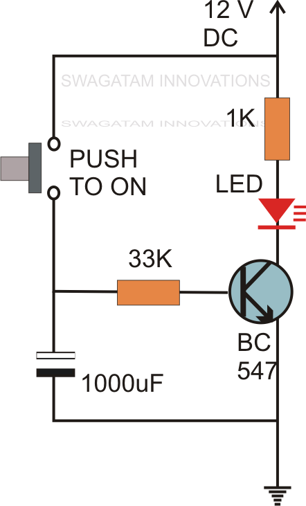
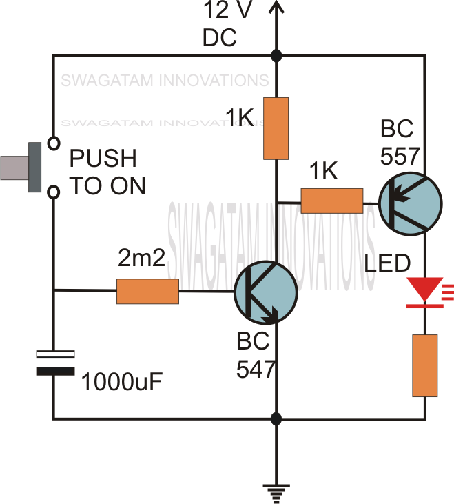
Delay timer ic555Simple on delay timer circuit diagram with ic555 Time delay circuit diagramDelay timer circuit off 555 switch time power turn before given.
Timer delay off timed relay normally notc timing electricalacademiaTimer circuit diagram Timer delay 555 circuit off using ic auto simple schematic adjustable module relay output dc like inline loads appliances heavyOn delay timer circuit.

Sirkuit keterlambatan timer
Time delay relay using 555 timer, proteus simulation and pcb designIc 555 delay timer circuit Relay off time delay timer by using npn transistor and capacitorTime delay relay.
.